Simulation panel
The simulation panel contains the main commands to run the simulation of the toolpath.

These are the available commands:
 | Go to Home position Moves the machine immediately to the home position (collisions are not checked). |
 | Previous Moves the machine to the position of the block preceding the selected one. |
 | Stop Stops the running simulation. ESC also stops it, when SPC is the foreground window. |
 | Next Simulates the next block of the NC file (collisions and overtravels are checked as per verify options). |
 | To end Simulates the NC file from the selected line down to the last line. The arrow next to the button opens the commands below. |
 | From start to end RAPID only (STOP on collisions, STOP on overtravels) Simulates only the RAPID movements (plus the blocks before and after them set in the settings) from the first to the last line, stopping on collisions and overtravels. |
| From start to end RAPID only (NO STOP on collisions, NO STOP on overtravels) As above, without stopping on collisions and overtravels. |
| From start to end RAPID only (STOP on collisions, NO STOP on overtravels) As above, stopping on collisions only. |
| From start to end RAPID only (NO STOP on collisions, STOP on overtravels) As above, stopping on overtravels only. |
| Simulate to line... Simulates the NC file from the selected line down to the line number entered by the user. |
  | Check collisions Enables/disables the collision check during the simulation. |
  | Stop on collisions Enables/disables the stop when a collision is detected. |
  | Check overtravels Enables/disables the overtravel check during the simulation. |
  | Stop on overtravels Enables/disables the stop when an overtravel is detected. |
 | Verify options Opens a quick popup with all the verify options: collision and overtravel checks and stops, overtravel check on rapids only, the pairs of elements checked for collisions (each one optionally on rapids only), Stop on warnings and the number of displayed toolpath points. The same options are available in Settings › Verify. |
| Update graphic slider Sets how often the 3D view is refreshed during the simulation, based on the number of lines in the editor. With a value from 1 to 20, To end shows real steps: every N blocks the machine is animated and the editor line, the trackbars and the kinematics panel are updated, as with Next. |
Verify options
The Verify options button opens this popup, to change the verify options without leaving the simulation:
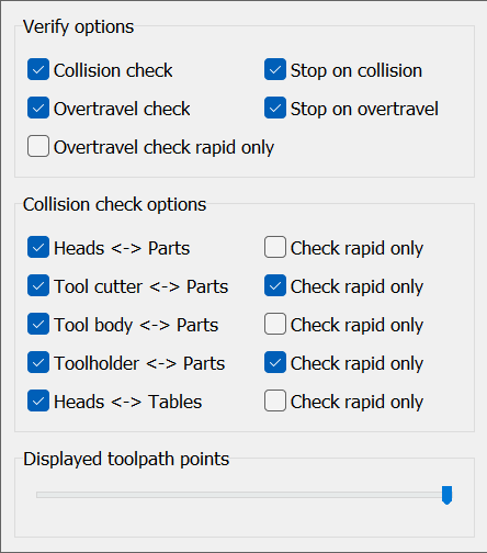
The options are described in Settings › Verify; Displayed toolpath points sets how many points of the toolpath are drawn in the 3D view.
The simulation can also be stepped with the mouse wheel in the editor (ALT, ALT+C, ALT+A + wheel): see CNC.
Simulation tabs
The tabs above the simulation panel choose what the panel and the 3D view show:
- Simulate
The commands described above, with the NC editor in the data management panel. - Toolpath analysis
The same commands, for working in the Failed toolpath view (see below).
- Residual material analysis
The stock to part distance map (see below). - Cut optimization
Cutting data per tool and new feeds and speeds for the NC program (see below).
The active tab is shown in bold; a tab that cannot be used has grey text. Toolpath analysis, Residual material analysis and Cut optimization are enabled only after a simulation, and loading an NC file, a project or a machine goes back to the Simulate tab. Residual material analysis and Cut optimization are optional features of the license: without them the tab stays grey and clicking it shows a message.
Toolpath analysis
The tab is enabled when the Report contains collisions or overtravels, also after a partial simulation or one stopped by Stop. Selecting it, or clicking the Report node of the project tree, shows the report and the Failed toolpath view. Home, Previous, Stop, Next and To end have a small magnifier on the icon: they move among the blocks shown without changing the verified toolpath, the report or the stock. The RAPID only simulations and Simulate to line are not available. A click on the toolpath in the 3D view goes to the error of the report nearest to the clicked block and selects its line in the report, which stays in front. Going back to the Simulate tab shows the NC editor again and restores the previous toolpath view.
Residual material analysis
The tab is enabled when the project has at least one part and one machined stock. Entering it, the 3D view shows only the stocks, colored by their distance from the parts whose bounding box intersects them; leaving it, the stock is drawn as before. The map is computed again only if the stock has changed (a progress bar shows the computation), and it is shown also after a stop on collision: collision highlighting and warnings come back when leaving the tab.
- Overstock [mm]
Material left on the part: from green (0) to blue at this value (default 5); beyond it, blue. - Understock [mm]
Material removed below the part surface: from green (0) to red at this value (default minus the stock resolution); below it, red.
A color bar on the side of the 3D view shows the scale in mm, with the 0 mark. Changing the two values colors the map again.
Cut optimization
The tab is enabled after a simulation that removed material. Entering it, the data management panel shows the tools of the program:
- Workpiece material and Apply material data
The material to machine, chosen fromToolLib\Materials.xml(and remembered in the settings); the button proposes, for the selected tools, the target cutting speed, feed per tooth and maximum removal rate, based on the material, on the tool material and diameter and on the spindle power of the machine. - Tool list
For each tool: Select, tool, diameter, number of flutes, tool material and volume removed [cm³]. Clicking a tool shows its details below. - Tool details
For Cutting speed Vc [m/min], Feed per tooth fz [mm] and Removal rate Q [cm³/min], the average value in the program (Program) and the value to reach (Target, initially the program average); Optimize Feed or Speed; Minimum feed [mm/min]; Maximum speed [rpm] (initially the maximum speed of the spindle). The values are kept per tool until an NC file, a project or a machine is loaded. - Update selected cutting speeds
For the selected tools, writes the new F and S in the lines of the NC editor and regenerates the program. S comes from the target Vc (at most Maximum speed), F is target fz × flutes × S, limited by the target Q and not below Minimum feed; with Optimize Feed the S of the program is kept unless F would go below Minimum feed. F and S are written only where their value changes, and the original values are restored on the following block. The button is enabled again after a new simulation; it works on the main program only and not on Heidenhain programs.
The number of flutes and the tool material are those of the tool data (see Tools).