Settings
Selecting this node displays the settings panel, divided into five sections: Application, Machine, Toolpath, Graphic, Verify. Save as default saves the settings for the next sessions.

Application
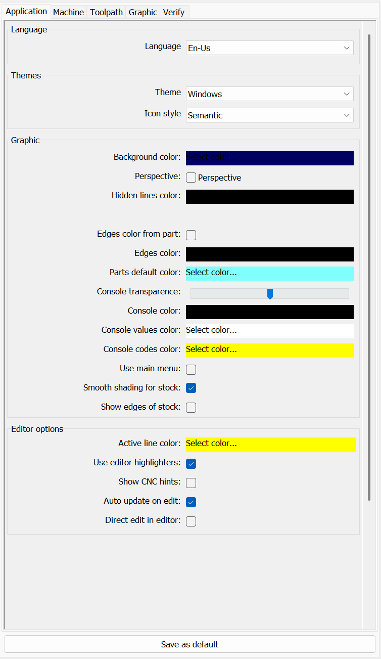
The application section contains the parameters of the user interface and of the 3D view.
- Language
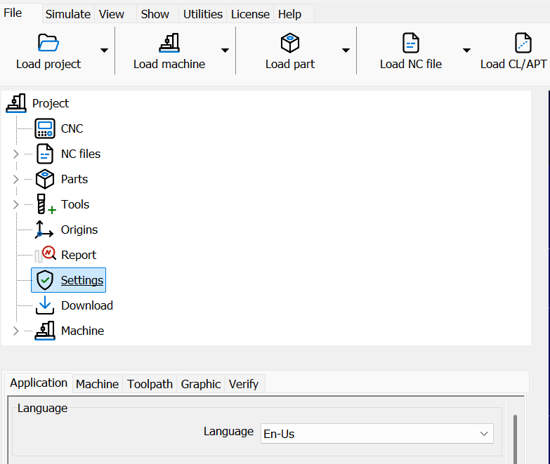
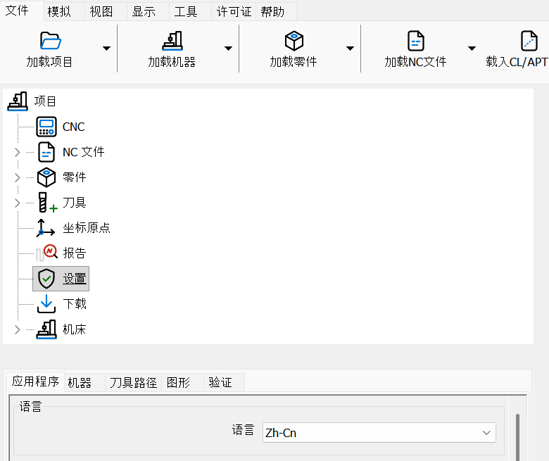
The language of SPC: English, Italian, German, French, Chinese, Spanish, Japanese. The language is changed immediately.
- Theme
The theme of SPC. Note: the new theme is shown after restarting SPC.
Windows 10 SlateGray theme: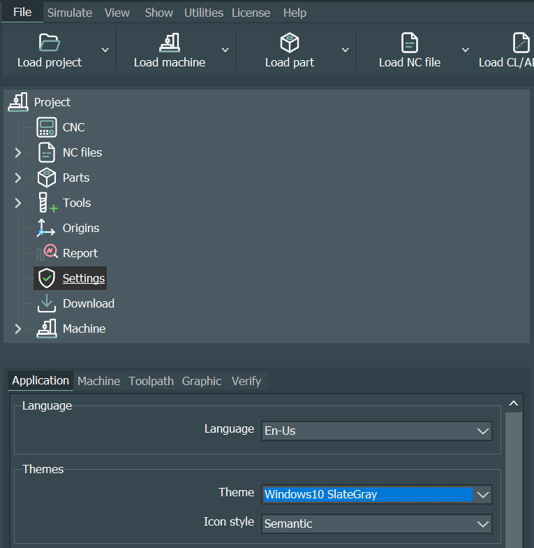
Windows 10 theme:
- Icon style
The style of the icons: Line, Duotone or Semantic (the style used in this help). - Background color
The background color of the 3D view. - Triad size, Navigator size and Logo size
The size in pixels of the axis triad, of the navigation cube and of the Arolo logo in the 3D view, applied immediately. 0 hides the triad or the cube; when not set, cube and logo are 80% of the triad (the logo at least 25 pixels). - Perspective
Perspective or parallel projection. - Hidden lines color
The color of the lines in hidden lines mode. - Highlight edges
Whether the edges are highlighted. - Edges color from part
Highlighted edges take the color of their part. - Edges color
The color of the highlighted edges, when not taken from the part. - Parts default color
The default color of an imported part. - Console transparence, color, values color, codes color
The appearance of the console in the 3D view. - Update graphic
Whether the graphic is updated during long movements. - Auto update on edit
Regenerates the NC file automatically after editing a line. - Use main menu
Uses the traditional main menu instead of the main menu panel. - Smooth shading for stock
Smooth shading of the stock surfaces. - Show edges of stock
Shows the edges of the stock. - Active line color
The color of the active line of the editor. - Use editor highlighters
Syntax highlighting in the editor. - Show CNC hints
Shows the description of the CNC codes while typing in the editor. - Direct edit in editor
The NC program is written and changed directly in the editor, instead of the Edit/Insert line field (see Direct edit). Off by default.
Machine
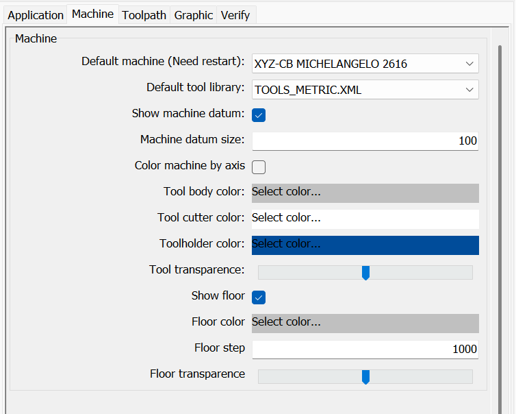
The machine section contains the parameters of the machine.
- Default machine
The machine loaded when SPC starts. Note: the setting is read at the next startup of SPC. - Machine datum size and Show machine datum
Size and visibility of the machine origin. - Grid color, step, transparence and Show grid
Appearance and visibility of the grid. - Tool transparence
The transparency of the tool. - Tool body color, Tool cutter color, Toolholder color
The colors of the tool and of the toolholder. The tool body is drawn in polished steel, slightly tinted by its color, and the toolholder in mirror chrome, with reflections that move when the view is rotated. The tool cutter is drawn with teeth and helical flutes chosen from the tool diameter and type; this is only its appearance: collisions and material removal use the same tool shape. - Floor color, step, transparence and Show floor
Appearance and visibility of the floor. - Color machine by axis
Draws each machine element with a fixed color for its axis, instead of the color of the machine definition (display only).
Toolpath
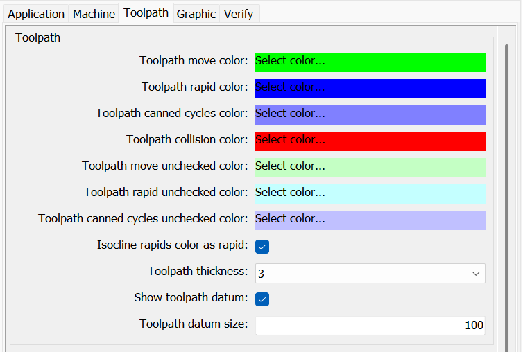
The toolpath section contains the parameters of the toolpath and of the stock.
- Toolpath move, rapid and collision colors
The colors of working movements, rapids and movements in collision. - Toolpath move and rapid unchecked colors
The colors of the toolpath not yet verified. - Unchecked toolpath on jump
The toolpath not yet verified shown after a direct positioning (click in the editor, Go to line, pick, Previous): All (default) or Active tool only, the toolpath of the tool active in the block (all of it when no tool is active). It applies also to the Rainbow, Isocline and By tool views. - Toolpath canned cycles colors
The colors of the canned cycles, verified and not verified. - Isocline rapids color as rapid
Whether the rapids in the isocline view keep the rapid color. - Toolpath thickness
The thickness of the toolpath, in pixels. - Show toolpath datum and Toolpath datum size
Visibility and size of the toolpath origin. - Linear smooth and Angular smooth
The linear and angular smoothing of the toolpath. - Number of blocks to check before and after RAPID
In the RAPID only simulations, the number of blocks checked before and after each rapid. - Toolpath coordinates at tool center
Whether the toolpath refers to the tool center or to the tool tip. - Default tool library
The tools library file used by default. - Displayed toolpath points
How many points of the verified toolpath are displayed. - The origins rotate with the tables / The origins translate with the tables
Whether the work origins follow the rotation and the translation of the machine tables. With a project open, these options and Toolpath coordinates at tool center change only the project (they are saved with it); without a project they change the default. - Min dexel size
The resolution of the stock for the material removal, in mm. - Stock mesh step
The step of the mesh used to draw the stock, in mm.
Graphic
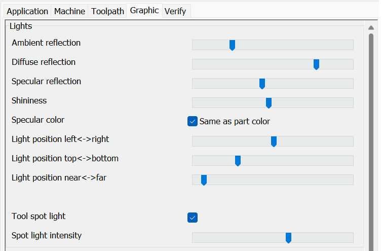
The graphic section contains the parameters of the lights of the 3D view.
- Ambient, diffuse and specular reflection and Shininess
The lighting values. - Specular color
Whether the specular color is the color of the part or white. - Light position left <-> right, top <-> bottom, near <-> far
The position of the light. - Tool spot light
Switches on a spot light along the tool axis that lights the area where the tool is working: it follows the movements and rotations of the heads, also in the tool point of view. It lights machine, parts, stock and tool, and does not cast shadows. On by default. - Spot light intensity
The intensity of the tool spot light (default 60%).
Verify
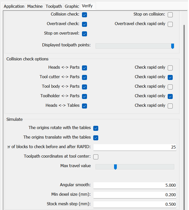
The verify section contains the parameters of the overtravel and collision checks. The same options can be changed quickly with  Verify options in the simulation toolbar.
Verify options
- Collision check and Stop on collision
Whether collisions are checked and whether the simulation stops on a collision. - Overtravel check and Stop on overtravel
Whether overtravels are checked and whether the simulation stops on an overtravel. - Overtravel check rapid only
Checks the overtravels on RAPID movements only. - Check triangles collision
Confirms the collisions on the triangles of the geometries (more precise, slower). - Max travel value
The length into which long movements are divided for the checks.
Collision check options
For each pair of elements the check can be enabled and, with Check rapid only, limited to RAPID movements:
- Heads <-> Parts
- Tool cutter <-> Parts
- Tool body <-> Parts
- Toolholder <-> Parts
- Heads <-> Tables
The last option, Stop on warnings (off by default), applies with Stop on collision on: when it is off, the WARNINGs (tangent moves, penetrations smaller than the stock resolution) stay in the report but do not stop the simulation; a real COLLISION still stops it.
Collisions of the tool cutter and of the tool body against the stock are confirmed on the real shape of the tool; rapid retracts along the tool axis are not reported, rapid movements inside or tangent to the material are (only for stocks with Check collision on). The collision message between the tool and a part or stock shows the penetration depth; a penetration smaller than the stock resolution is reported as a WARNING: the stock is still marked in red, and the simulation stops only with Stop on warnings on. When the depth of a RAPID movement inside the material is smaller than the stock resolution, the resolution is shown.