3D graphic panel
The 3D graphic panel interactively displays the whole three-dimensional environment of the simulator.
Console
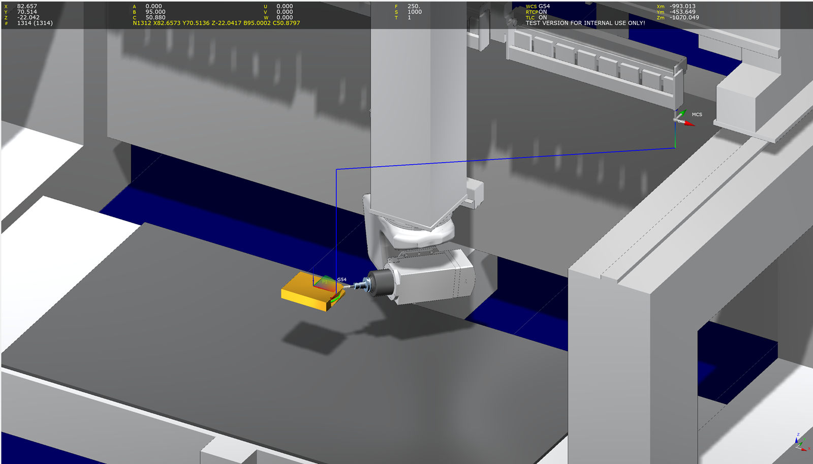
The console, in the upper part, reports the position of the axes and the main data of the numerical control:
- X, Y, Z: coordinates of the linear axes relative to the active origin;
- A, B, C: values of the rotary axes;
- U, V, W: coordinates of the parallel axes relative to the active origin;
- F: feed rate;
- S: spindle speed;
- T: ID of the active tool;
- #: current line number;
- RTCP: current RTCP state;
- Gxx: current origin;
- X(), Y(), Z(): absolute values relative to the machine origin;
- the active NC block.
Mouse commands
| Right button + move | Rotate Rotates the 3D view around the point under the cursor. |
| Wheel | Zoom Zooms in and out on the point under the cursor. |
| Middle button + move | Pan Moves the 3D view. |
| Right click | Context menu Quick access to the most used commands. |
| Left click on the toolpath | Pick Selects the block of the clicked segment: the machine moves to that position and the editor shows the line. Only the segments shown by the active toolpath view can be picked. In Toolpath analysis the click goes to the error of the report nearest to the clicked block. |
| Left click on a part | Select part Selects the node of the clicked part, fixture or stock in the project tree. |
The context menu of the 3D view has the Standard views submenu and, after it, the Special views submenu with  Tool view,
 Split view and
 Section view.
Navigation cube
The navigation cube in the top right corner of the 3D view shows the orientation of the scene. Clicking a face, an edge or a corner turns the camera to that view, with an animation along the shortest way; the region under the mouse is highlighted. The small house button goes back to the initial view. The Arolo logo is shown under the cube.
Tool view
Tool view (CTRL+T) divides the 3D view: on the left the interactive main view, on the right the view from the tool tip, which follows the tool. The trackbars under the view set Field of view, Height and Side offset (from -300 to 300) of the tool view. Tool view and Split view are alternative.
Split view
Split view (CTRL+D) divides the 3D view into two views of the scene, each with its own camera (rotation, pan, zoom). The active view, chosen with the last click or wheel, has a blue frame and receives the standard views; the console is in the left view.
Section view
Section view (menu View, toolbar, context menu of the 3D view) opens a bar at the bottom of the 3D view with the section planes:
- X, Y, Z
A plane for each machine axis, each with its check box, its offset (field and trackbar) and Flip to hide the other side. - Tool axis
A plane that contains the tool tip and the tool axis and turns towards the camera, hiding the half of the scene in front of the tool; it follows the tool during the simulation and works in each view of the Split view (not in the Tool view). Flip hides the other half. - Options
Cut objects chooses what is cut: machine, parts, stock, tool, toolpath (default parts and stock). Machine frame / Workpiece frame chooses whether the X/Y/Z planes are fixed in the machine or follow the workpiece when the tables move.
Machine, parts, stocks and tool cut by a plane show a hatched cap with the color of the object; the cut also applies to the shadows and to the pick of the toolpath. The planes are only graphic: they do not change the simulation, the collisions or the material removal, and they are not saved.